5 Pin Flasher Relay Wiring Diagram
To do this, refer to the 5 pin relay wiring diagram. This diagram provides a clear illustration of how each terminal needs to be connected to the circuit. Once the connections are established, the relay can be secured to the mounting bracket and wired according to the manufacturer's instructions. When installing a 5 pin relay, it is important.

5 Pin Led Flasher Relay Wiring Diagram Wiring Diagram
The 5V relay module can be used to control a load such as a lighting system motor or solenoid it can also be used to switch ac or dc voltages the maximum voltage and current that the 5V relay.

Relay Wiring Diagram 5 Pin Stylesync Me Fair blurts.me Automotive
Try EdrawMax and make 5 Pin Relay Wiring Diagram easily https://bit.ly/3EK0wL7Explore 5 Pin Relay Wiring Diagram and free use and edit 5000+ diagram examples.
Automotive Relay Wiring Diagram
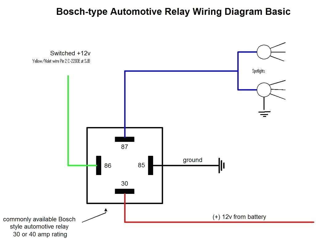
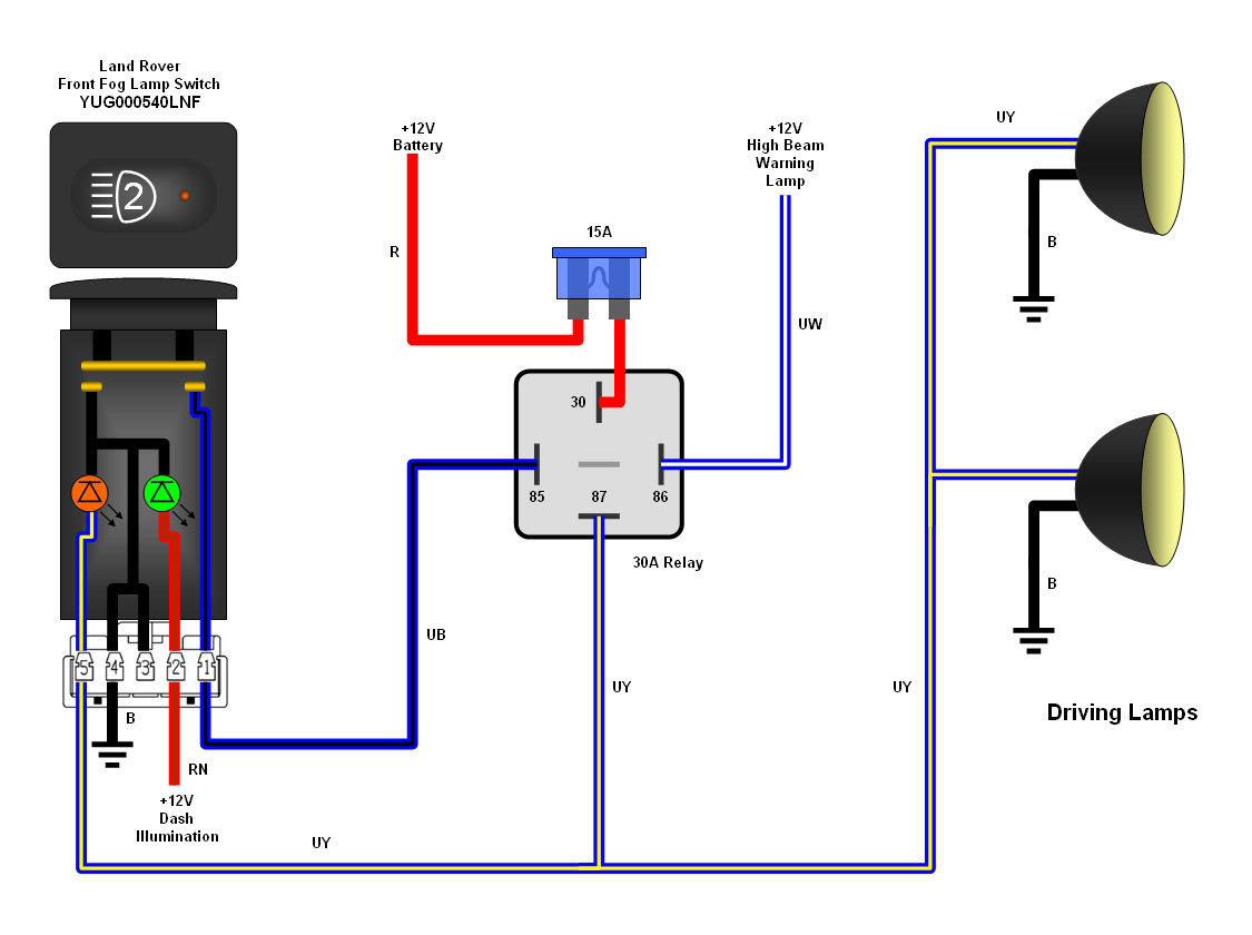
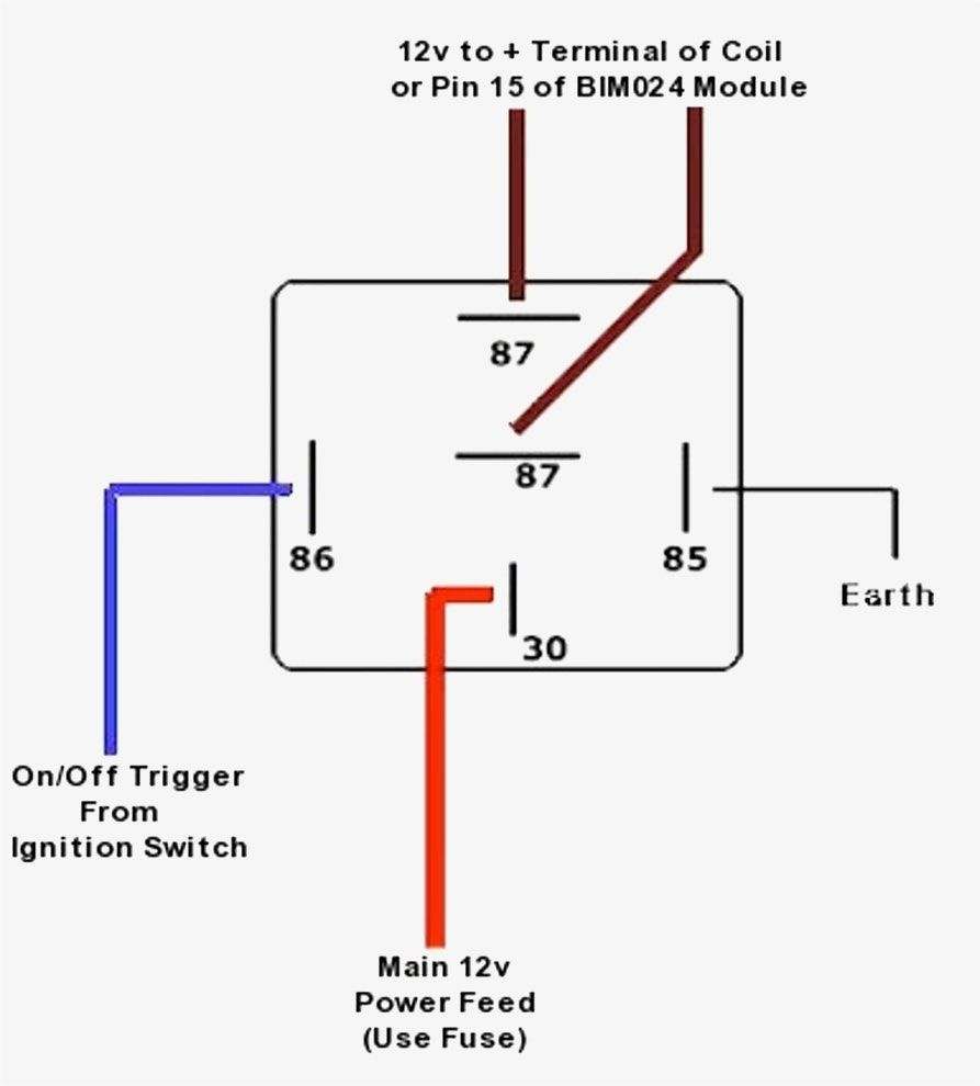
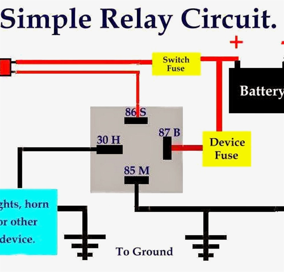
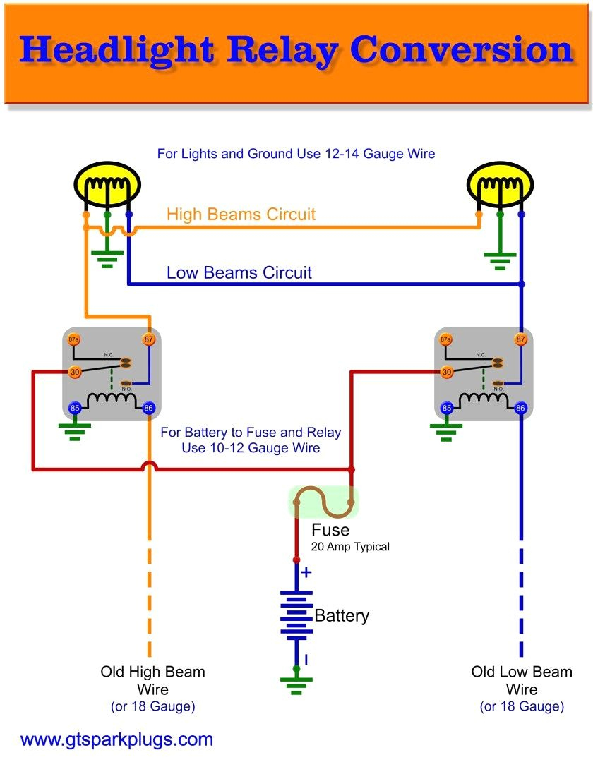
How to Wire a 5 Pin Automotive Relay. Pins 87/30/85/86/87a . Bosch Style. Fans / Fuel Pump / Lights Wiring Rescue 74.1K subscribers Subscribe Subscribed Share 547K views 3 years ago.
5 Pin Relay Wiring Diagram Driving Lights Cadician's Blog
The 5-pin relay can also be used for one purpose by not connecting the 87a to anything, but at that point, you can just get a 4-pin relay. Summary . Relays are a great solution for a variety of electrical systems. Allowing the low electrical current to control the high current through the relay makes for a safer and more reliable system.
Bosch 5 Pin Relay Wiring Diagram Allove Relay Wiring Diagram 5 Pin
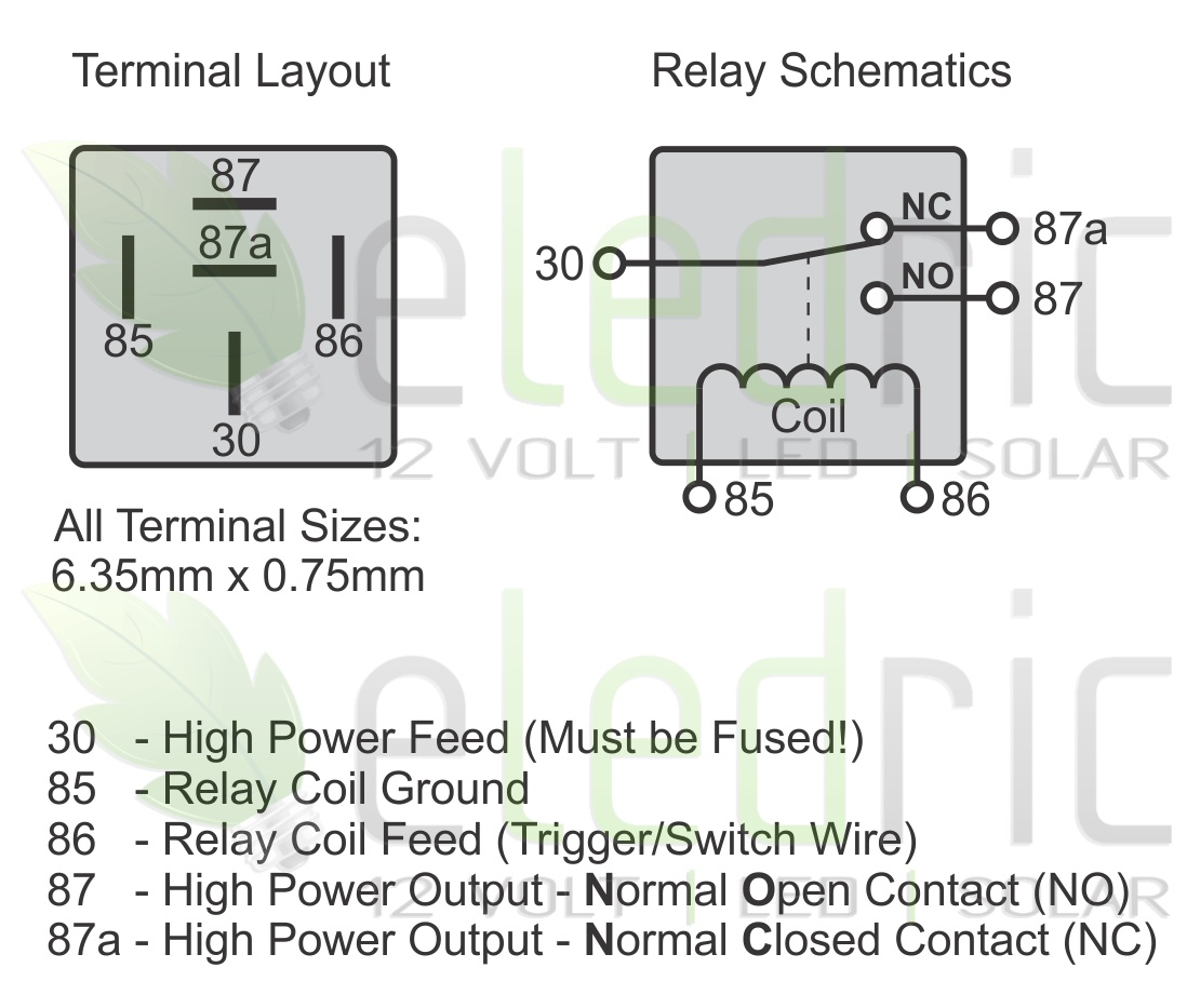
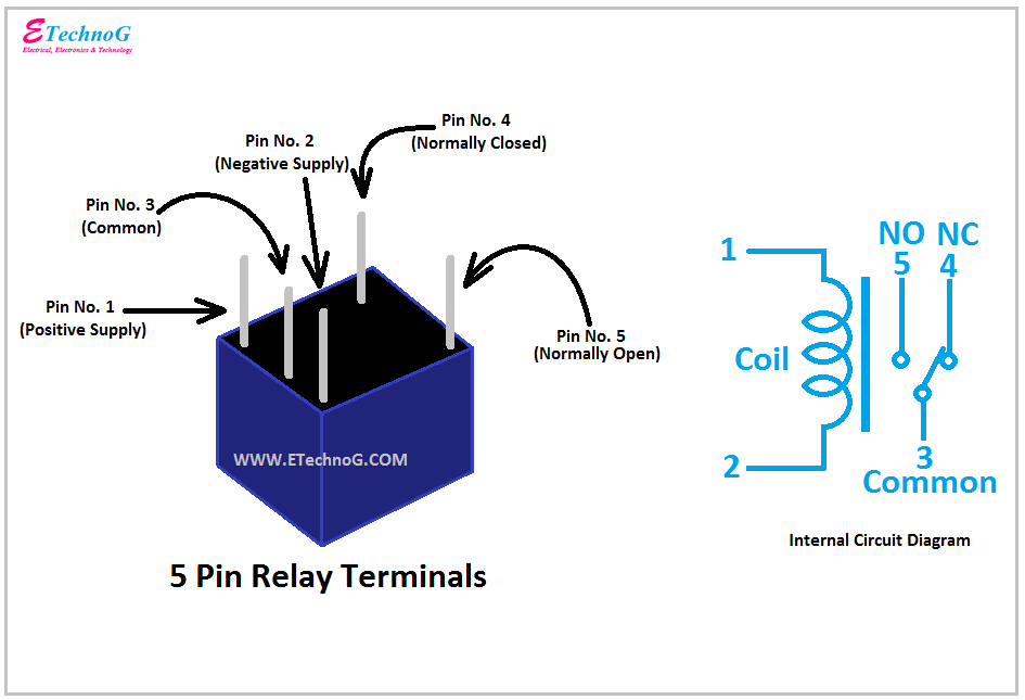
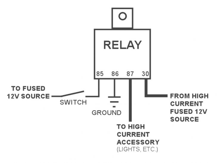
5-Pin-Relay-Wiring-Diagram-On-Relay-Case According to DIN 72552 Standard, each pin of a relay is numbered 85, 86, 30, 87, and 87a. You need to know that a relay has two circuits, a coil circuit (also called a "low current circuit", or "inductive circuit"), and a high-amperage circuit.
How A 5 Pin Relay Works Youtube Relay Wiring Diagram 5 Pin Wiring
A 5 pin relay wiring diagram is a pictorial illustration of the physical connections and physical layout of an electrical system or circuit. It shows how the electrical wires are interconnected and can also show where fixtures and components may be connected to the system.

Relay 5 Pin Wiring Diagram Wiring Harness Diagram
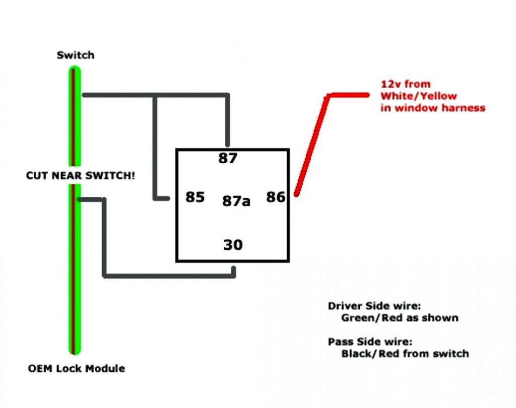
Here are the steps: Steps for wiring a relay Relay pin layouts and functions are not standard, so they may vary between manufacturers. Always check the markings on the component or the accompanying datasheet or conduct a continuity test. The relay will connect to three other components in the circuit: A power source A controller, such as a switch
5 Pin Relay Wiring Diagram Ground
This completes the wiring diagram for your 5 pin relay, allowing you to control your lights with ease. Remember to double-check all connections and ensure that the wiring is secure before testing the system. By following this wiring diagram, you can effectively control your lights using a 5 pin relay. Whether you are installing lights on a.

5 Pin Led Flasher Relay Wiring Diagram Wiring Diagram
To wire a 5 pin relay, you'll need the following parts: A 5 Pin Relay The correct wiring harness for the application Electrical Tape or Heat Shrink Tubing (optional) Wire Crimping Tools (optional) Important Relay Terminology Before attempting to wire a 5 pin relay, it is important to understand the following terminology and definitions:
Bosch Relay Wiring Diagram 5 Pole Manual EBooks 5 Prong Relay
The 5-pin relay diagram provides a visual representation of how the different pins on the relay are connected. These relays typically consist of five pins: two for the coil, which is the electromagnet that controls the switching action, and three for the switch, which allows the circuit to be interrupted or completed.
12V Relay Wiring Diagram 5 Pin Wiring Diagram
A 5 pin relay is a versatile component that can be used in various automotive applications. It is commonly used to control electrical circuits in vehicles, such as turning on lights, activating horns, or operating motors. The pins on a 5 pin relay are labeled differently and have specific functions that need to be understood for proper wiring.

5 Pin Wire Diagram Pin Rocker Switch Wiring Diagram Image Wiring
The wiring diagram for a 5-pin relay typically includes all of the same components as a 4-pin relay, plus an additional power source for the control circuit. When wiring a relay, it's important to use proper gauge wire and ensure correct polarity to avoid damage to the relay or other components.

5 Pin Relay Wiring Diagram Use Of Relay
A 5-pin relay is an SPDT relay, which means that the contacts of the relay are single pole double throw. In single pole double throw relay, we have one pin is common, 2nd is normally close and 3rd is normally open. Two pins for the coil. This relay can be used for different types of controlling or switching.

Wiring Diagram For Automotive Relay
How To Wire a 4 or 5 Pin Relay Rocky X TV 21.9K subscribers Subscribe Subscribed 6.9K Share Save 630K views 6 years ago In this video I show you how to wire a 12 volt automotive Bosch.
12 Volt 5 Pin Relay Wiring Diagram Pickenscountymedicalcenter 12V
Ⅰ What are 5 Pin Relays Used for? A relay with five pins typically has two to operate the coil and three to incorporate an SPDT switch function with a common and a normally open contact (open when the relay is unenergized and connected to common when the relay is energized) and a normally closed contact with the opposite function.